 Intermediate
Writing your first SPIN program
A brief introduction to SPIN, the language of the Propeller, and your first Blink program
What is SPIN?
SPIN ( get it? Spin a Propeller? ) is the language of the Propeller chip. It's actually unique to the Propeller, found nowhere else. Surprisingly it's also an interpreted language. This means it's not actually compiled into a set of instructions that the Propeller chip understands natively, but is instead run in a tiny interpreter inside the chip1.
Propeller's native language is PASM, or "Propeller Assembly." It's a little beyond the scope of your Propeller HAT journey, though, so we'll ignore it for now.
What makes up a SPIN program?
Every SPIN program consists of functions, variables, constants and data indicated by "Block Designators". These concepts are common to most programming languages, but SPIN is strict about how and where they appear.
The block types in SPIN are:
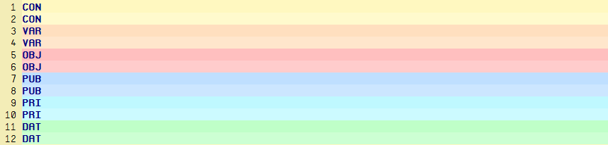
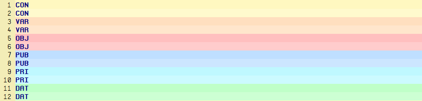
CON- Declares a block of Constants, such asLED_PIN = 1VAR- Declares a block of Variables, such asled_state := 0OBJ- Declares a block of Objects, these load external code for you to use in your program
( a bit like Python's import )PUB- Declares a single public method- if you were loading your code as an object, you could call this methodPRI- Declares a single private method- this would be hidden when loading your code as an objectDAT- Declares a block of data, this is often used to store chunks of Propeller Assembly
In Propeller IDE, each of these blocks will be displayed with its own distinct background colour, and adjacent blocks of the same kind will have alternating shades to differentiate them. This gives most SPIN examples their colourful and somewhat controversial looks:
The CON block is also used to declare some important settings such as the Clock Mode, and Crystal Frequency, which
let your program know what sort of environment it's running in.
A bare-bones SPIN program might look something like this:
CON
  _CLKMODE = xtal1 + pll16x
  _XINFREQ = 6_000_000

  MY_LED_PIN = 0 ' Use pin A0

PUB main
  DIRA[MY_LED_PIN] := 1 ' Set the LED pin to an output

  repeat ' Repeat forever
    OUTA[MY_LED_PIN] := 1  ' Turn the LED on
    waitcnt(cnt + clkfreq) ' Wait 1 second
                           ' cnt is the clock tick counter,
                           ' clkfreq is the number of clock ticks in a second
    OUTA[MY_LED_PIN] := 0  ' Turn the LED off
    waitcnt(cnt + clkfreq) ' Wait 1 second
Let's break this down step-by-step...
CLKMODE and XINFREQ
These might look like complicated arcane magic at first, but they're really nothing to be worried about. On Propeller HAT these two lines will always be the same.
_CLKMODE is being set with the value xtal1 + pll16x to state that we want to use the external crystal oscillator,
and set the system clock to its value, multiplied by 16x using the PLL2.
_XINFREQ is simply set with the frequency of the external clock. On Propeller HAT we use a 6Mhz crystal, so that's 6000000.
We use understores, which are ignored by SPIN when found in numbers, to make the big number read clearly at a glance.
Assigning MY_LED_PIN
Propeller HAT has 30 user pins from 0 to 29, pins 30 and 31 are tied to your Pi's serial port for communication.
To assign our LED constant we pick one of the available pins ( labelled A0 to A29 on the board ) and use the corresponding
number. Because we're assigning a constant, we use the "Constant Assignment" operator which is simply =:
MY_LED_PIN = 0 ' Use pin A0
DIRA and OUTA
Behind the scenes of Arduino you'll find something very much like these. They are known as Registers. DIRA and OUTA both refer to physical, 32-bit locations onboard the Propeller chip itself and the values of each bit in these locations correspond directly to the Direction ( DIRA ) and Output Value ( OUTA ) of each hardware pin.
Think of a register as 32 physical on-off switches which you can change from your code, since this is fundamentally what it is.
Note: In the Propeller world every single core or cog has its own DIRA and OUTA register, and the values of these are "OR'd" together to form the final direction and output values of each pin. If any cog tells a pin to output a 1, that pin will output a 1, and if any* cog sets a pin to an output that pin will be an output. Keep this in mind, or it'll almost certainly trip you up when you start using more than one core!
Here are some of the ways you can assign a state to the output and direction registers:
OUTA := %00000000_00000000_00000000_00000001
OUTA[0..3] := %1000
OUTA[0] := 1
OUTA[0]~~       ' Set to 1, high
OUTA[0]~        ' Set to 0, low
When setting any variable within SPIN you should use := instead of = since = is the "Constant Assignment" operator
and should only ever be used to assign constants.
I don't use OUTA[0]~~ or OUTA[0]~ because I think they're unnecessarily obtuse and confusing. OUTA[0] := 1 and OUTA[0] := 0 are longer, but easier to understand at a glance.
repeat
SPIN uses a repeat command, this is similar to a for or while loop and there are many ways to change its behaviour which we'll cover in later examples. Right now we'll just use repeat on its own to create an infinite loop.
Notice that the lines underneath repeat are indented? This is because, like Python, SPIN uses indentation as syntax (to convey meaning ). In this instance, the indented lines are the ones we want to be repeated. If you're a keen pythonista, you should also take note that there's no ":" on the end of "repeat".
repeat
  ' Everything you want to be repeated
  ' should be indented under the repeat command
waitcnt
SPIN's waitcnt command, meaning simply "Wait for Counter" is similar in purpose to Python's sleep but conceptually a little different. What you're actually doing here is waiting for the clock counter to reach a specific value. Normally you'll want to wait some multiple of seconds, and it just so happens that the value clkfreq always contains the number of clock ticks in a second. Multiply it by 10 and you get a 10 second wait, divide it by 10 and you get a tenth of a second wait, easy!
waitcnt(cnt + (clkfreq/10)) ' Wait 0.1 seconds
waitcnt(cnt + (clkfreq*10)) ' Wait 10 seconds
Wiring up your Propeller HAT
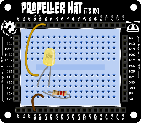
To see the result of this code, you'll need an of LED plugged into outputs A0, like so:
Uploading the code
To build and upload the code, you'll need either Propeller IDE on your desktop/laptop computer, or on your Raspberry Pi.
On the Pi it should be as simple as hitting the "Run" arrow ( the arrow pointing to the right ) and it'll upload
right onto your Propeller HAT. If this doesn't work you should try propman. When you compile/build your program in
Propeller IDE it will generate a binary alongside the .spin file.
To flash a compiled binary you can use a binary built on the Pi, or with one you've uploaded from your desktop/laptop computer:
propman blink.binary
The default should ensure it gets uploaded to Propeller HAT and run. You should see your LED blink!
Further Reading
- 1 Watch a video about the difference between a compiler and interpreter: https://www.youtube.com/watch?v=_C5AHaS1mOA
- 2 "PLL" stands for "Phase-locked Loop", read more about it here: http://en.wikipedia.org/wiki/Phase-locked_loop