 Intermediate
Building a Swarm of Sound-Reactive Jellyfish
How we made a bunch of glowing jellyfish for EMFCamp, powered by Raspberry Pi Pico 2.
Find out how we created a light up swarm of sound reactive LED jellyfish to decorate our #EMFCamp village!
Why?
It's not our first time attending Electromagnetic Field, but it is the first year that my friends have been organised enough to set up a village. To celebrate, we thought we'd build a collaborative art installation and as we're called Sheffield-By-The-Sea, what better than a bunch of light-up jellyfish to pulse in time to all the great sounds that happen at EMF 🎶
This guide won't be a prescriptive how-to, but more of a recipe for what we created and some of the problems that we encountered, which might be helpful if you're planning a group project of your own.
Etymology
Electromagnetic Field is a "non-profit camping festival for those with an inquisitive mind or an interest in making things: hackers, artists, geeks, crafters, scientists, and engineers". It happens once every two years in a spider-filled field in Herefordshire, and attending is one of the most inspiring things that you can do with a weekend. We'll be referring to it as EMF in this article for brevity.
Apparently a group of jellyfish can be collectively referred to as a 'fleet', 'smack', 'bloom', 'swarm' or 'fluther'. We'll be throwing those terms around at random.
The Prototypes
Before we could start figuring out how to deploy jellyfish at scale, we needed to come up with a prototype, so we could solve any early issues and figure out what supplies we'd need. Here's Jelly the first:
Jelly I had a 3D printed frame, a Raspberry Pi Pico for a brain and an I2S microphone, all plumbed into a breadboard. It also had a PIR sensor (we were toying with the idea of making them motion activated). Here's our first design for the frame:
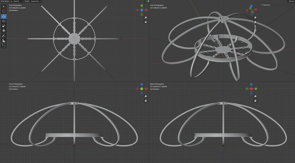
For our second prototype we switched up the LEDs, making the central ring more closely spaced and added more tentacles. We also added LED noodles to the top, and made a bunch of changes to the frame (more on that later).
Our prototype cover/diffuser was made of white ripstop nylon which had the advantages of being waterproof and diffusing the LED light nicely. We ended up not using this for the final version though - making the cover fit the frame was time consuming and difficult as the fabric had zero stretch.
We started writing our software in MicroPython, but switched to programming in C++ for the final version (more on this later too). We also switched to a Pico 2, and saw considerable performance benefits from this.
Bill of Materials
Once we were happy with the prototype, we draw up a bill of materials for our final fleet. We planned to make 8-10 jellyfish, and each one required:
- A Raspberry Pi Pico 2 W.
- An INMP441 I2S microphone (widely available online)
- 96 'pixels' of Addressable RGB LED strip (144 pixels per metre).
- 48 'pixels' of Flexible RGB LED wire.
- 4 x 300mm LED Noodles
- A custom Jellyboard (not essential, but it made wiring things up much easier)
- 2x 6mm tactile buttons
- A 3D printed frame/skeleton (yes we know jellyfish don't have skeletons)
- A fabric cover (two 60cm circles of fabric, plus 1m of elastic thread).
- Assorted scraps, ribbons etc to decorate
- Long micro-USB cables or speaker wire to supply power
Why Pico 2 W?
Pico 2 W is an affordable, capable microcontroller. The RP2350 chip that it uses has some particularly nifty functionality that makes it good for our use case - PIOs (Programmable Input/Outputs). These can be used to move bits around without tying up the CPU and we found they came in handy for controlling multiple sets of LEDs and listening for microphone inputs at the same time.
We don't use the wireless functionality of Pico 2 W in this project so we could have used the non wireless version. However, using the 'W' version means we have the option to repurpose the jellyfish as smart lighting, notification lights or other fun connected projects after the festival.
More about the LEDs
We're using three kinds of LEDs in this project:
- Dense addressable RGB LEDs (AKA Neopixels) for the core ring.
- Dangly addressable RGB LED wire for the tentacles.
- LED noodles to imitate a bioluminescent glow from the top of the jellyfish.
The LED noodles are not addressable so we can't change their colour, but we can make them dimmer or brighter by using PWM (Pulse Width Modulation) - that's turning them on and off really fast.
3D Printing the Frame
The frame of the jellyfish needed to be light enough to be hung easily from tents and other rickety structures, so 3D printing was the obvious construction choice. We also wanted the frames to be as big as possible when assembled, but we needed to make sure the largest parts (the hub and the ribs) could easily fit onto a standard ~20cm x 20cm 3D printer bed, so we could churn them out on our respective 3D printers.
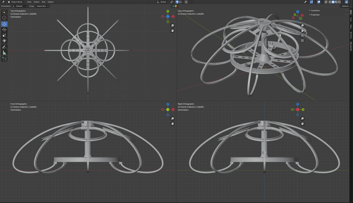
Each jellyfish frame was made up of the following parts:
- 1x pillar
- 1x base
- 8x ribs
- 4x loops
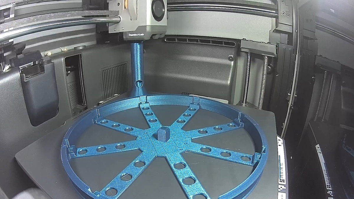
The central pillar holds everything together and is used to route the wires. The ribs hold everything together with tabs at both ends that click into place, meaning no glue, screws or other hardware is needed to assemble the frame. There is space underneath the base to attach the Jellyboard PCB, and the holes in the base give us plenty of places to thread wires or attach tentacles.
We used a selection of transparent, white, purple, sparkly blue and glow in the dark filament, and each Jelly used about 230g of filament. We printed some out of PLA and some out of PET-G - we're yet to find out if the PLA ones warp / melt / otherwise misbehave if it gets really sunny!
The 3D printing files can be found here:
🚀 Note from the future - we only had problems with one brand of (glow in the dark) PLA made by Geeetech, which warped after being left in a very hot car for a day and resulted in a few bendy jellies. The PETG and Elegoo and Bambu PLA we used held up fine.
Designing the Jellyboard
We designed a custom PCB with a landing for the Pico and contacts to make soldering the LEDs and microphone to it easier. This is mainly for convenience - we could have just soldered wires between our Pico brain and the LEDs, but it would have been a lot less fun to do multiple times.
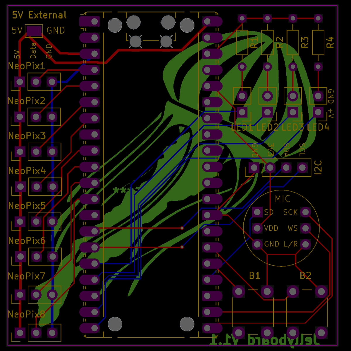
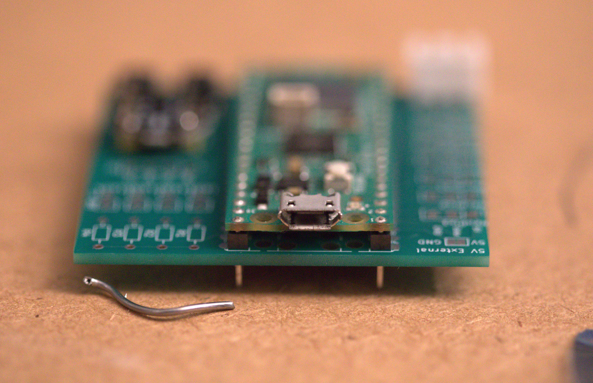
The board is designed so that you can either solder the castellated pads on the Pico direct to the board, or solder on a Pico with headers.
Another consideration was how to feed power to the LEDs. Each Jelly can draw about an amp, so we need to consider where all this power is going to come from - it's too much to draw from the Pico's GPIO pins. The addressable LED terminals on Jellyboard are wired to the Pico's VBUS pin, which draws 5V power from the main power supply (USB or the external power pads). In the field, we'll have the option of using a USB power-bank or speaker wire connected to an external power supply.
We designed the Jellyboard PCB using Kicad and had it made by JLCPCB. The cheap shipping from China took a while to arrive, so be sure to allow adequate time if you're doing something similar! Here's what the final boards look like:
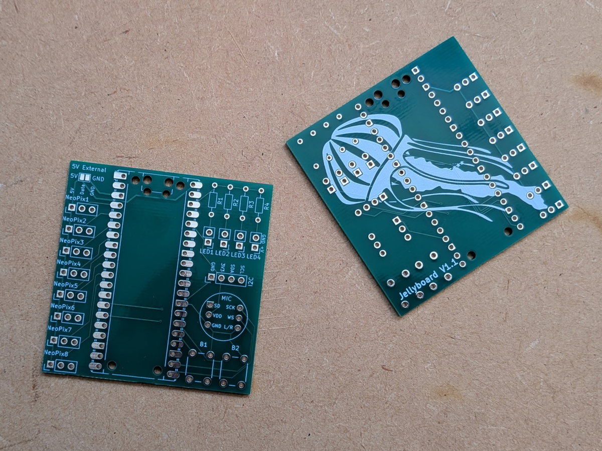
You can see the PCB design files here:
Assembling the Electronics
Making Your Friends Assemble PCBs In Your Living Room
First order of business was soldering the Pico, the buttons, the mic and lots of wires onto the Jellyboards. In the middle of a heatwave.
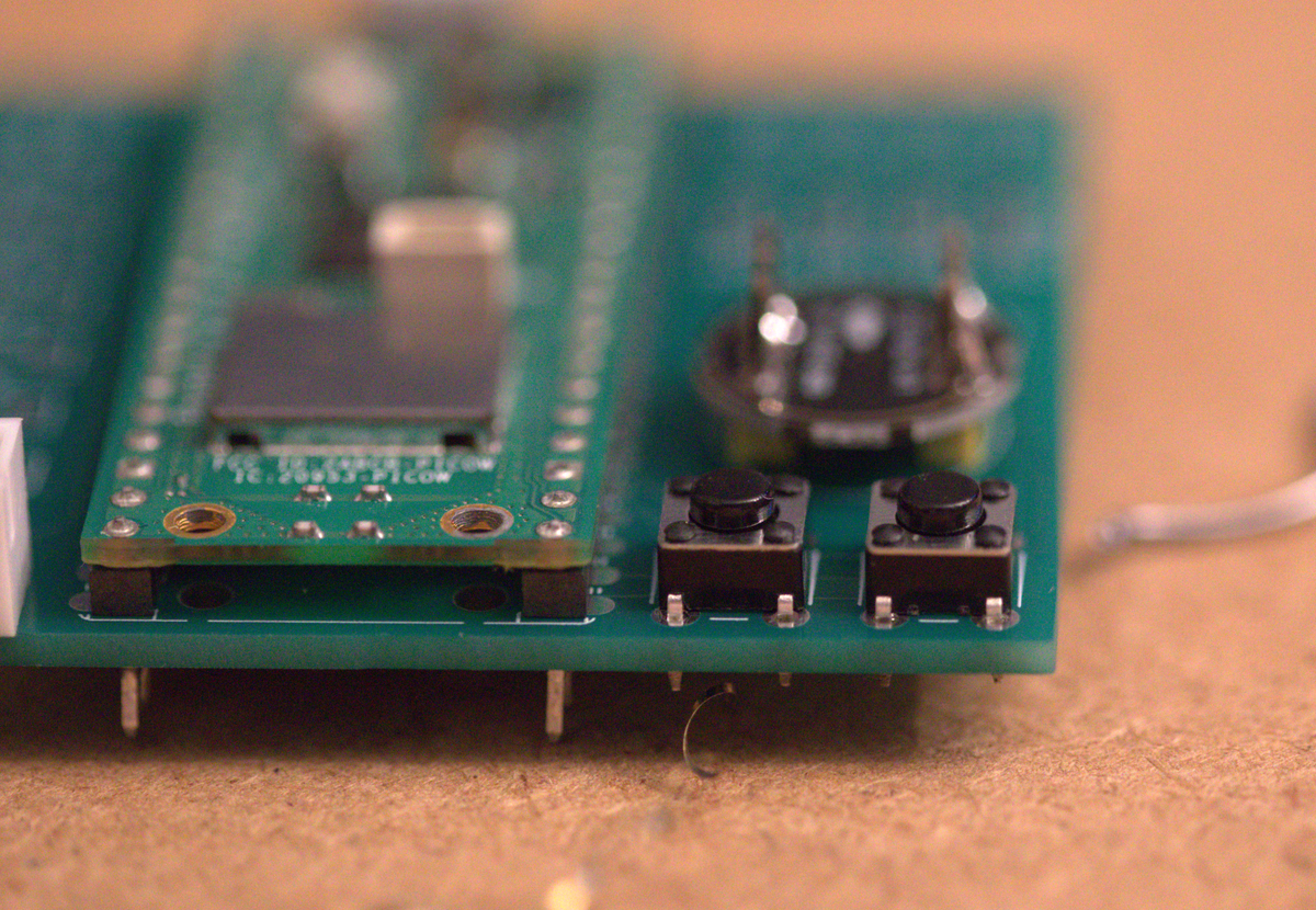
Here's Simon working away - it's so warm his soldering iron has melted.
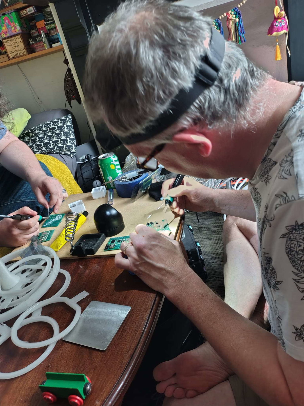
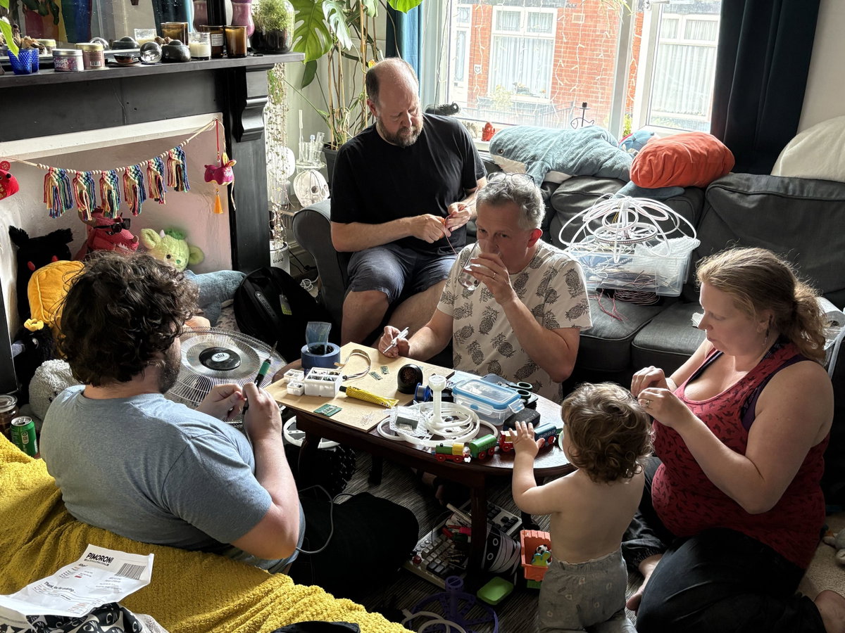
Economies were made by completing these steps production line style and we ultimately didn't have to resort to child labour - Bean got to continue playing with trains.
This is what the boards looked like with all the components in place:
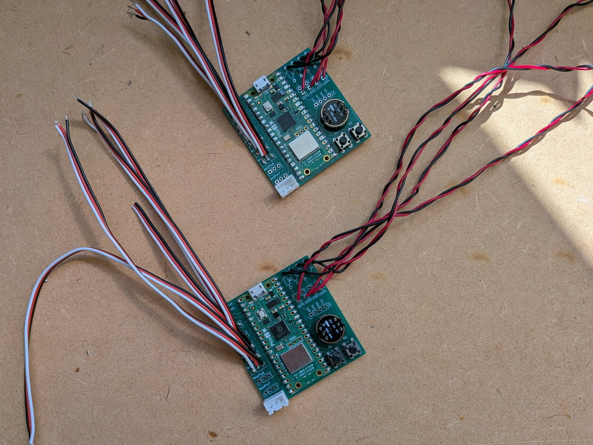
Wiring Up The LEDs
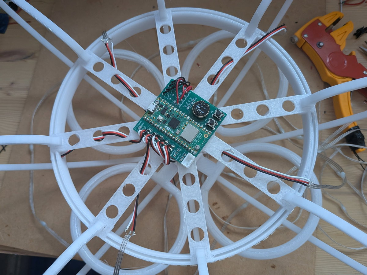
The boards attach to the 3D printed base using two M2 x 6mm bolts, through the Pico's own mounting holes.
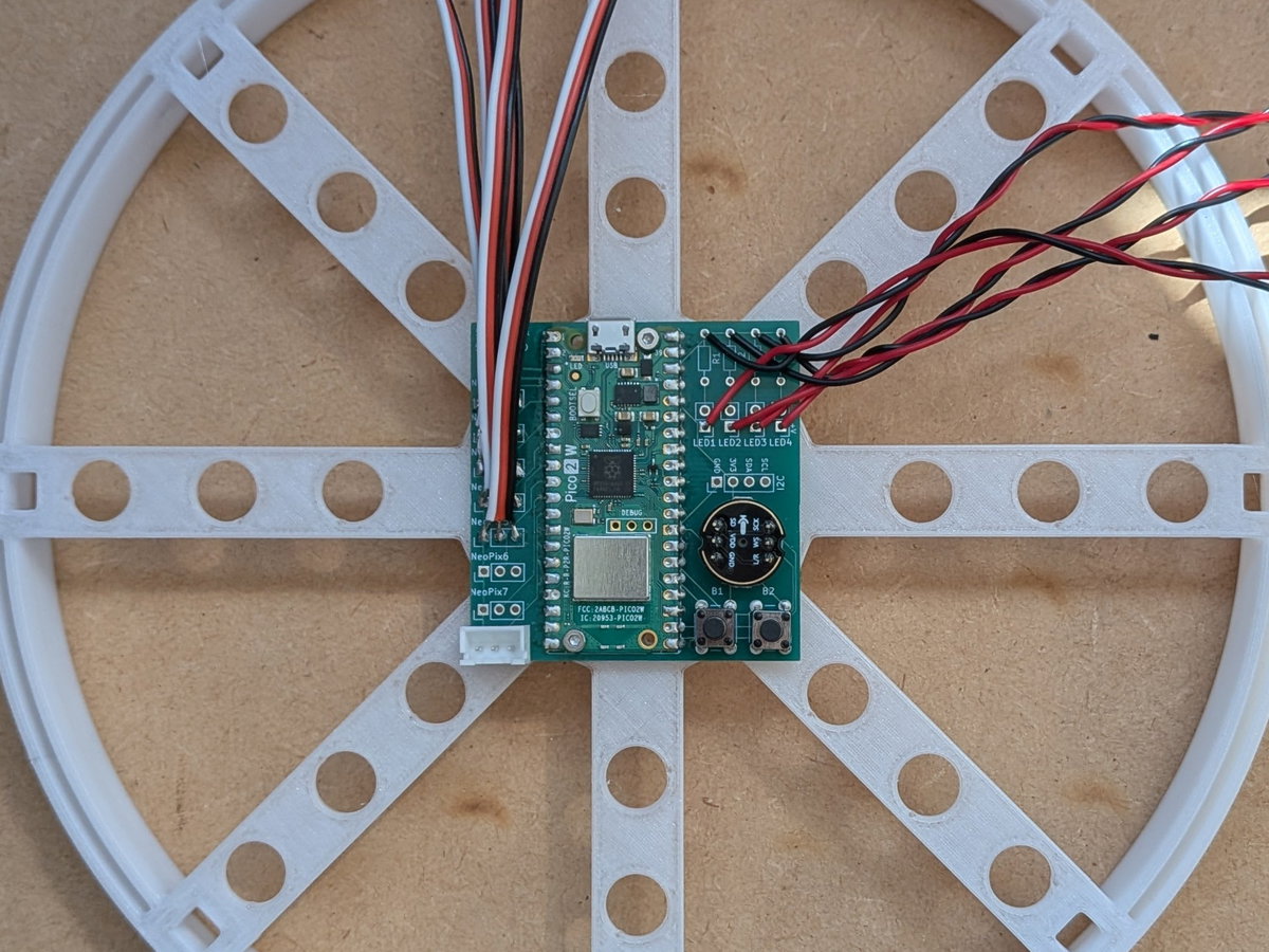
The LED wires are threaded through the frame. There is a little hole on the outer edge for routing the ring LED's wires through, then the tentacle wires attach to every other spoke, going clockwise. (Getting this consistent is important, otherwise the software won't behave in the same way on each unit).
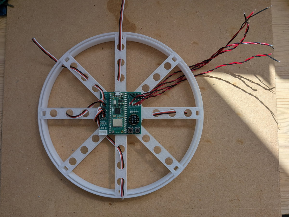
Here you can see the ring wire pushed through the hole, and the LEDs soldered on. Our 3-core servo wire has the colours in an unhelpful order for LEDs - here black is ground, red is data, and white is +5v.
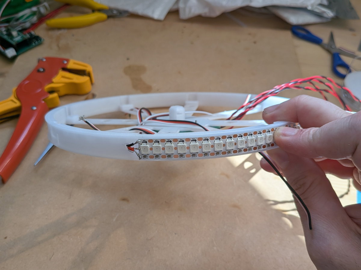
The ring is sized to take 96 LEDs.
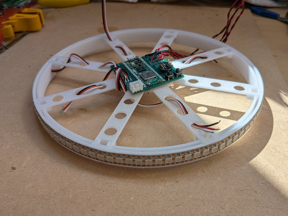
The tower friction-fits to the top of the base. Don't worry, the ribs will hold it in place later on.
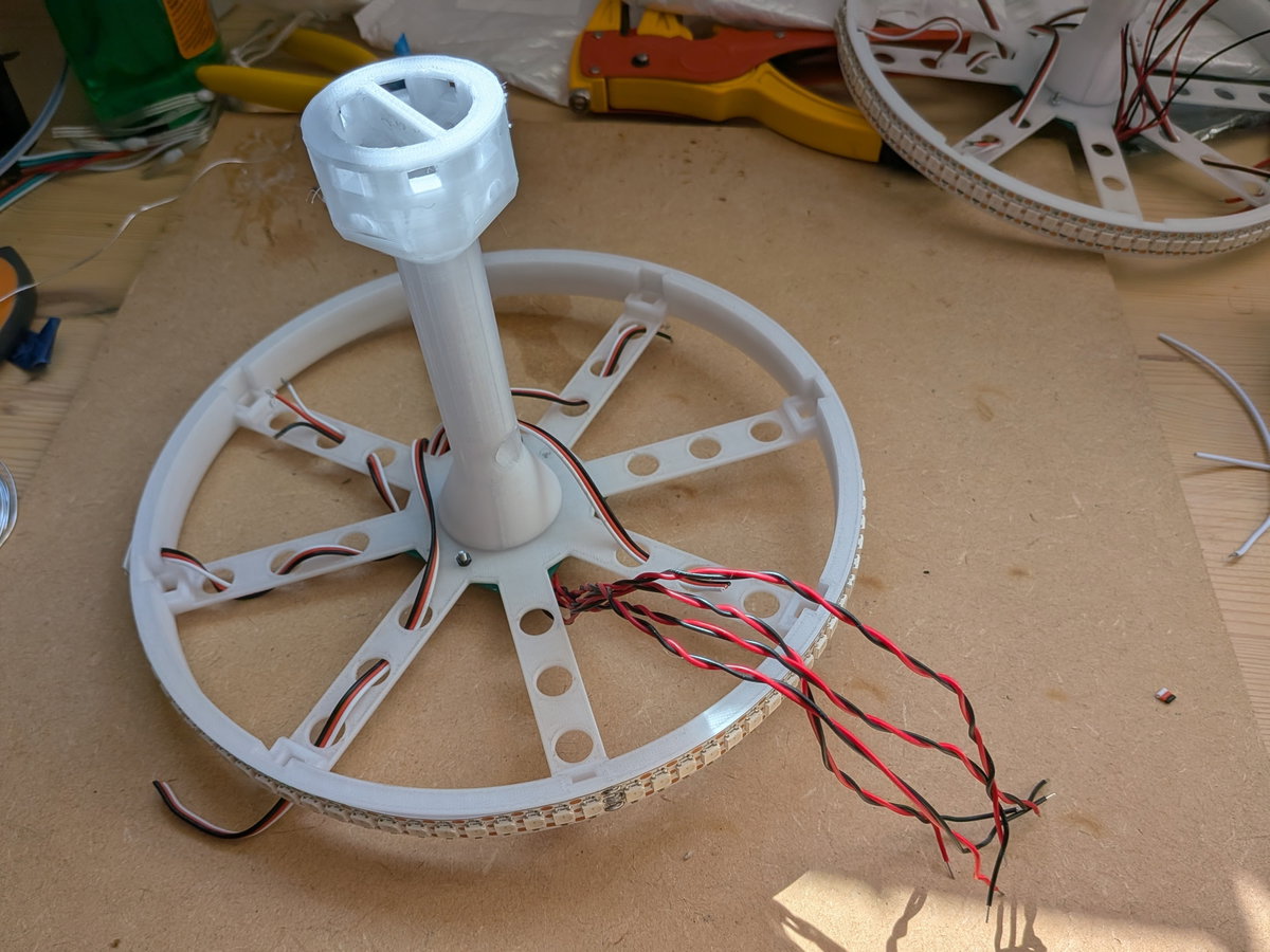
Here we're starting to route the noodle wires up the centre of the tower. The connection 'LED1' should be above the first tentacle wire, going clockwise.
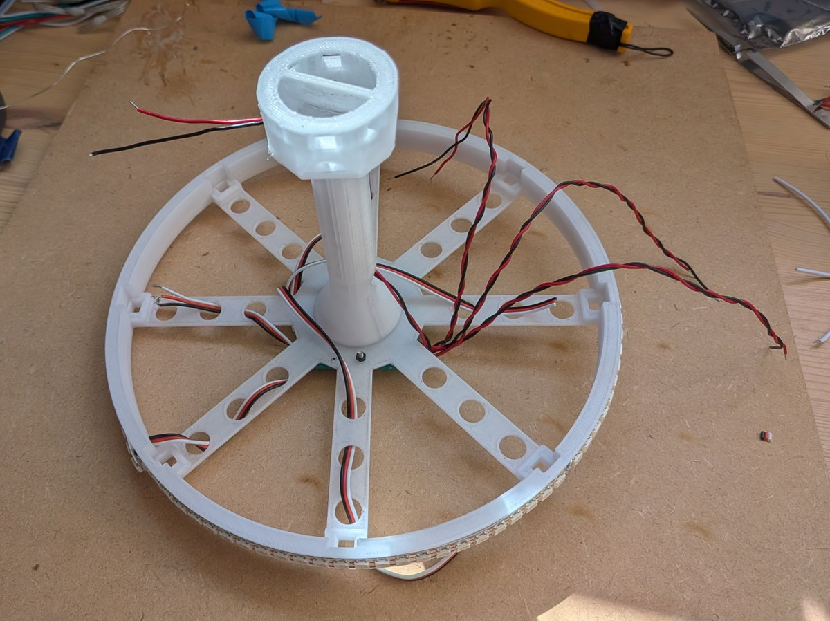
Here all four pairs of wires are routed up the centre of the tower and through the holes at the top.
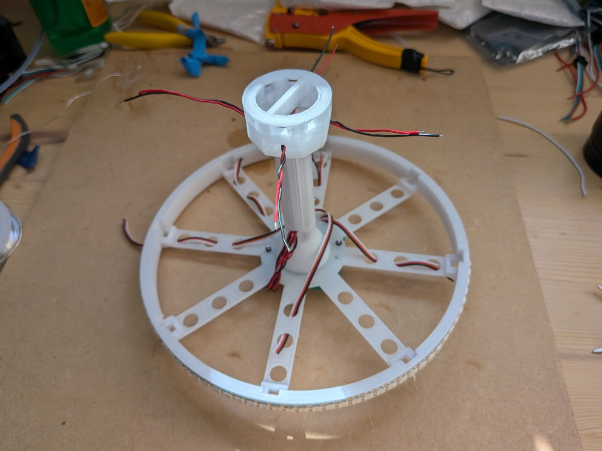
A shot from underneath, with all the cables routed.
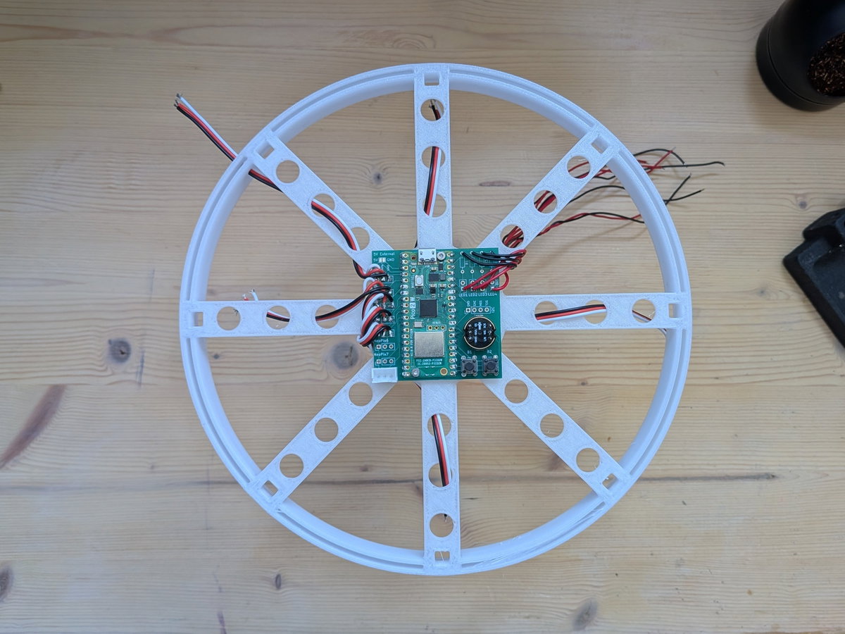
The loops press-fit into the slots on the tower. Little clips should hold them in place and no glue is needed (unless you break one).
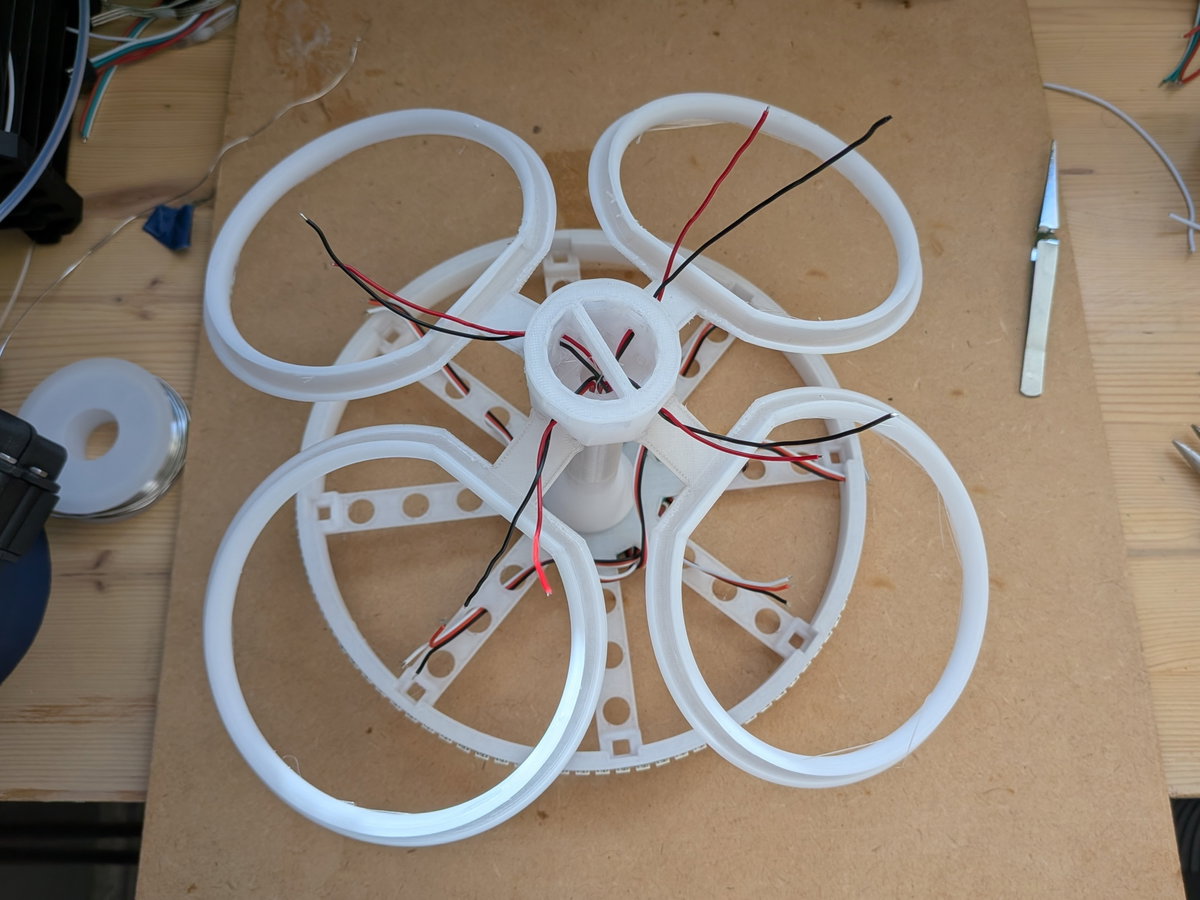
Trimming the wires, and soldering on the noodles.
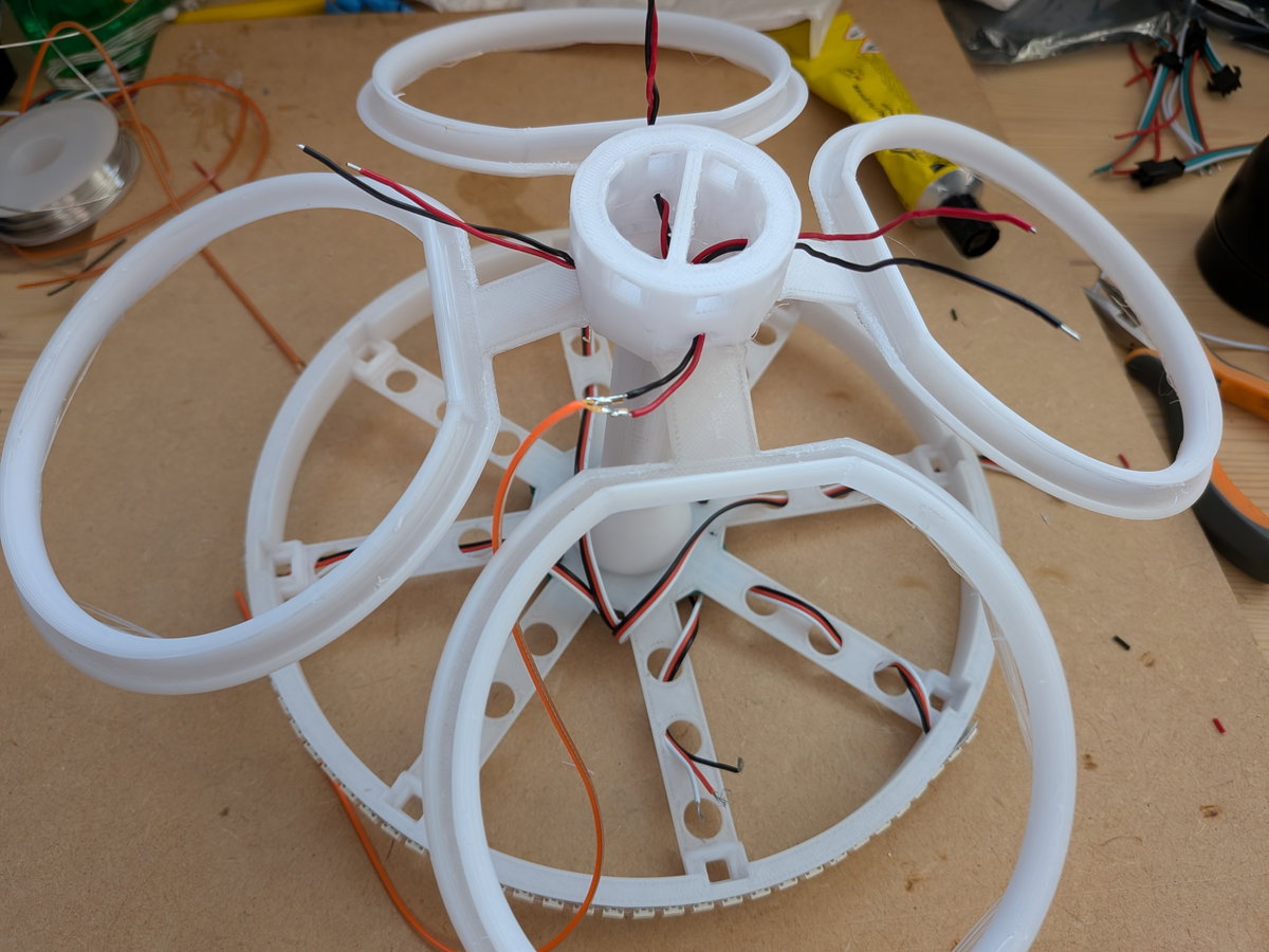
Here we needed a little bit of glue (we used UHU glue) to hold the noodle into the loop. For this jellyfish we used the type of noodle that has both connections at the same end, so we also added a dab of glue between the contacts to stop them touching and shorting out.

Repeat for all four noodles!
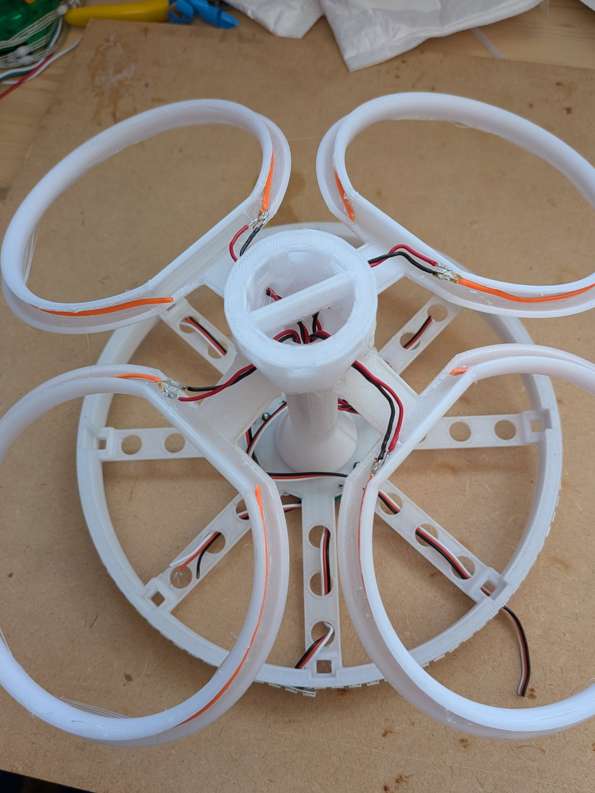
One the noodles are in place, the ribs can be clipped into place, which will give the fabric shape and hold the tower in place. This is what it should look like from the top.
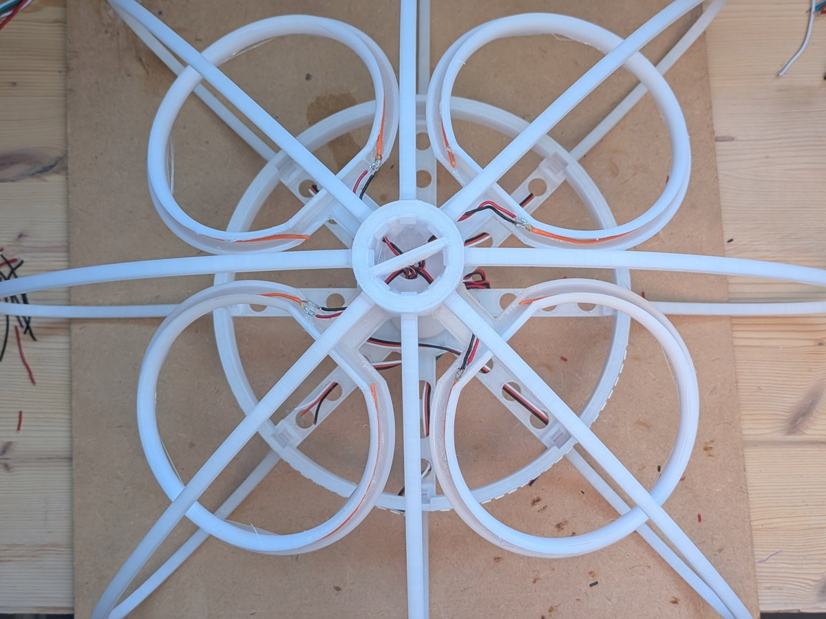
Last job is to turn it upside down and solder the four sets of tentacles. Each is 12 LEDs long. We gathered the tentacles between the 5th and 6th LEDs and cable tied them the spokes, to give a loop before the last 6 LEDs hung freely.
Making the Covers
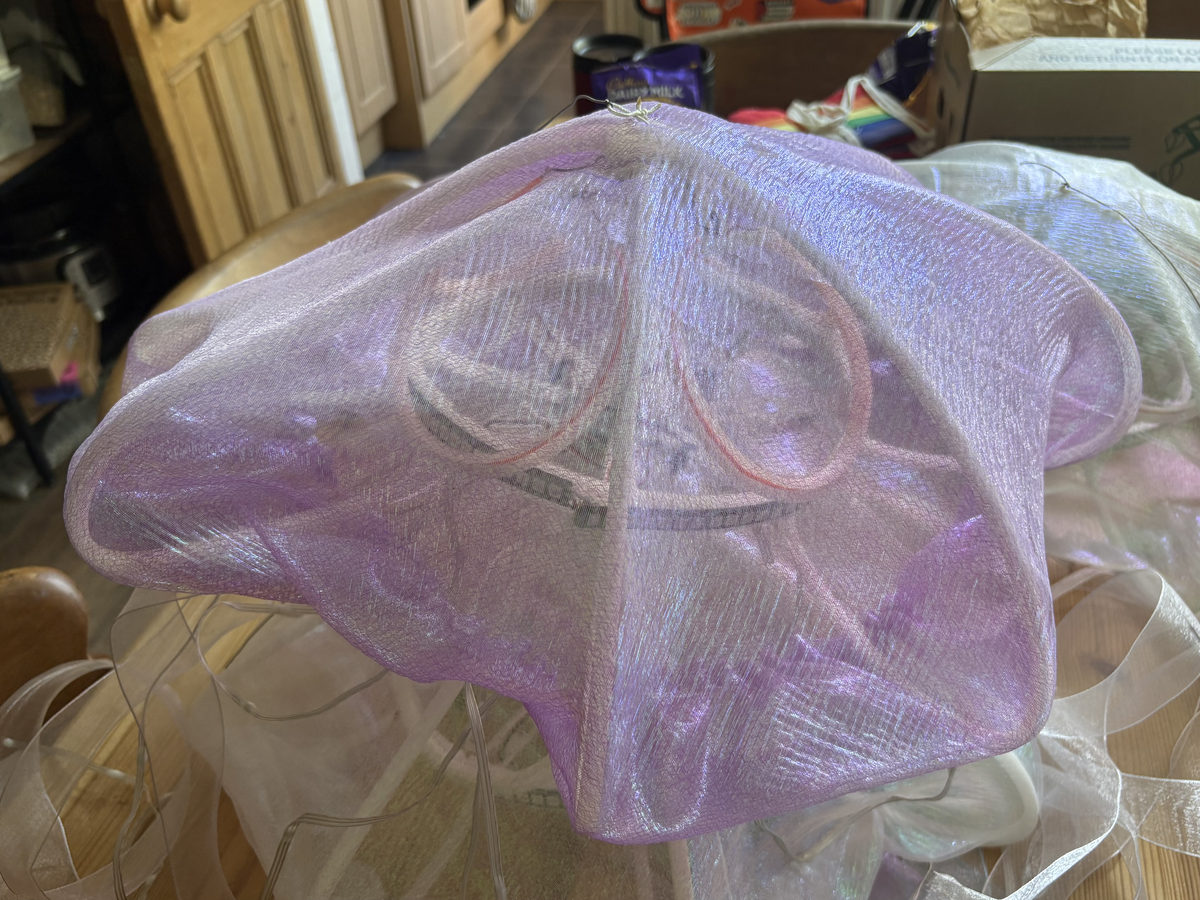
We made the final fabric covers (the epidermis, if you want to get technical, or the 'fancy shower caps' if not) out of ✨rainbow crystal organza✨. This fabric was a pain to sew and doesn't provide much diffusion, but reflects the light beautifully.
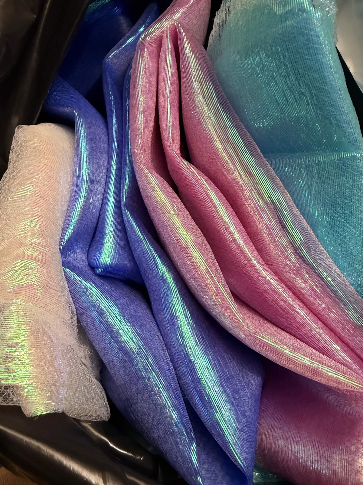
For each jellyfish, we folded the fabric in half and cut out two circles of roughly 50-60cm diameter. We decided to use two layers, as a single layer was a bit too sheer.
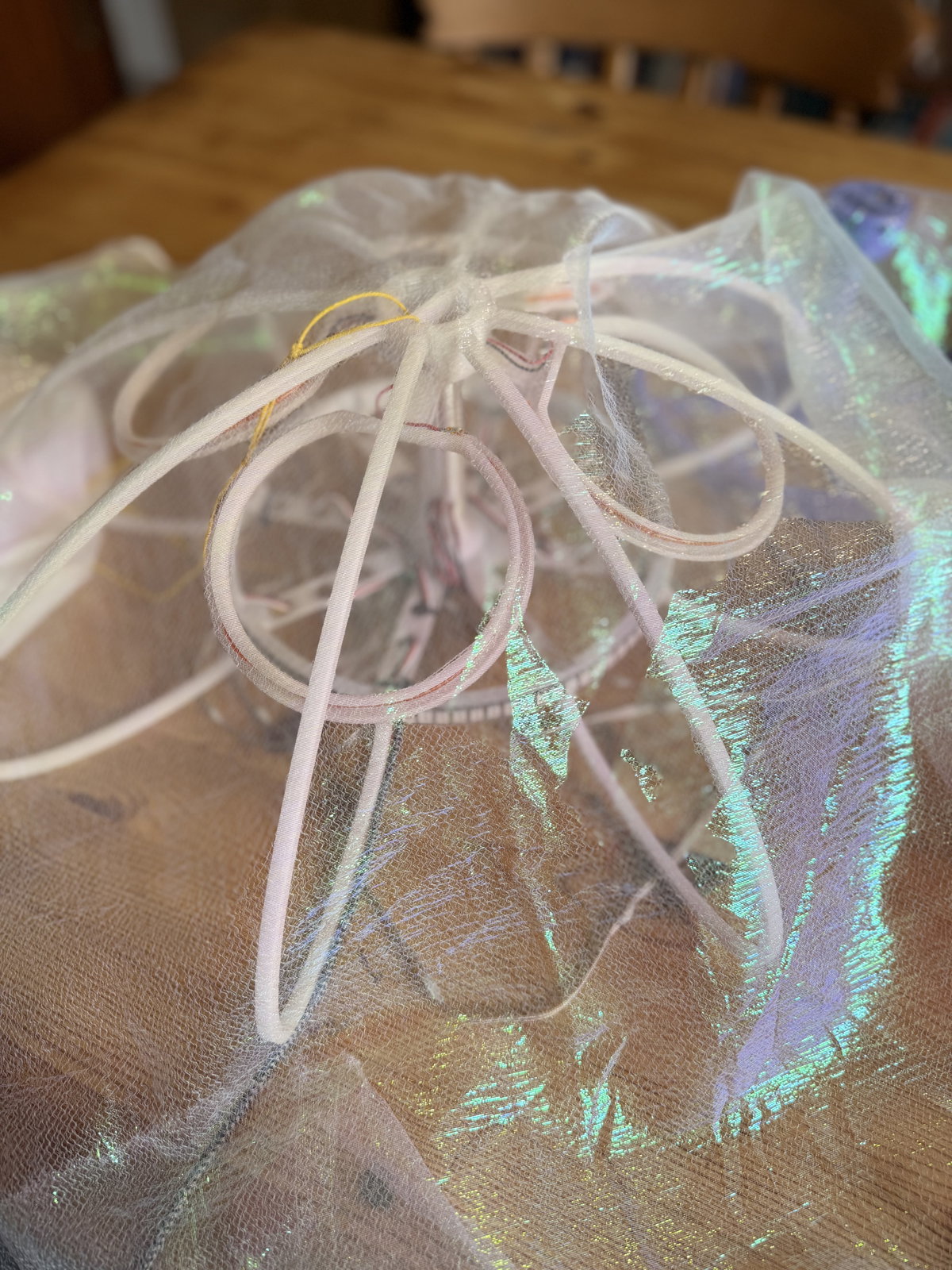
We put both circles together, then sewed round the edge of with a 6mm seam allowance, leaving a gap so we could turn the whole shebang inside out. Once we'd done that, we top-stitched round the edge. If you're using a fabric that's less prone to fraying you might be able to get away with less seaming (or no seaming at all!), but doing it this way seemed to do a pretty good job of keeping the loose edges encapsulated.
We sewed around the circle one more time about 10mm in from the topstitching, to make a channel to thread the elastic into.
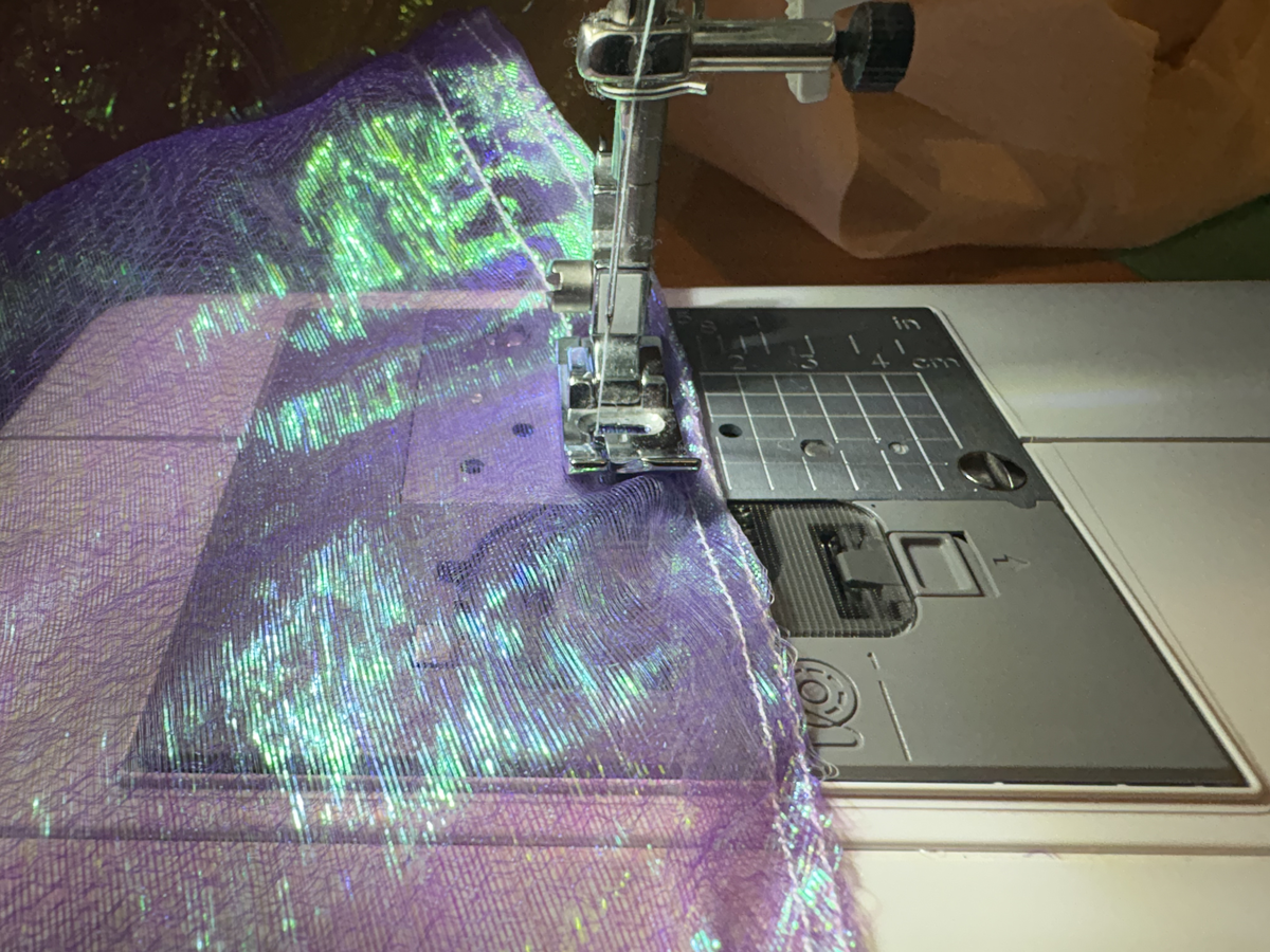
Each jelly used about 1m of 'elastic string' (I stole this from a bracelet making kit). Tying the elastic to a safety pin made it easier to thread into the channel.
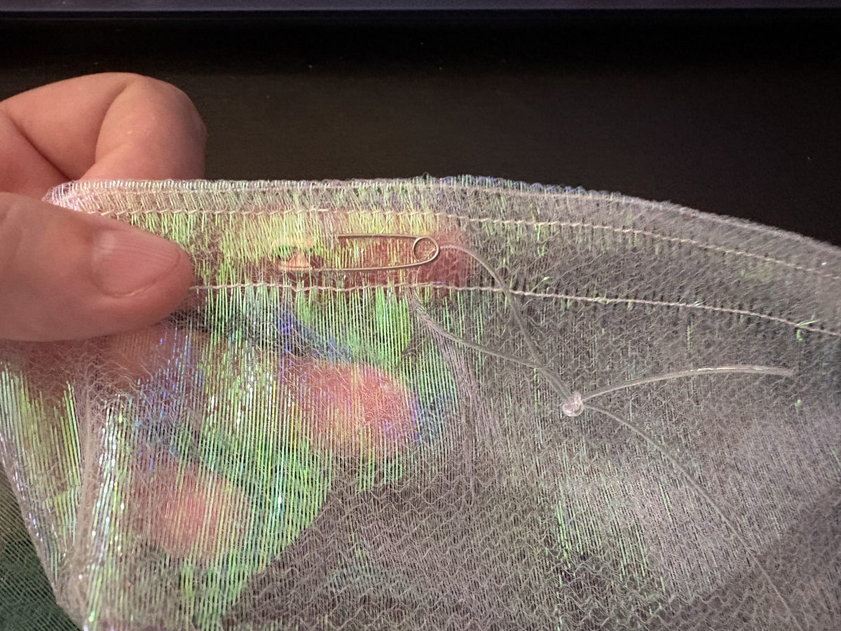
Cover complete! Now repeat a bunch more times.
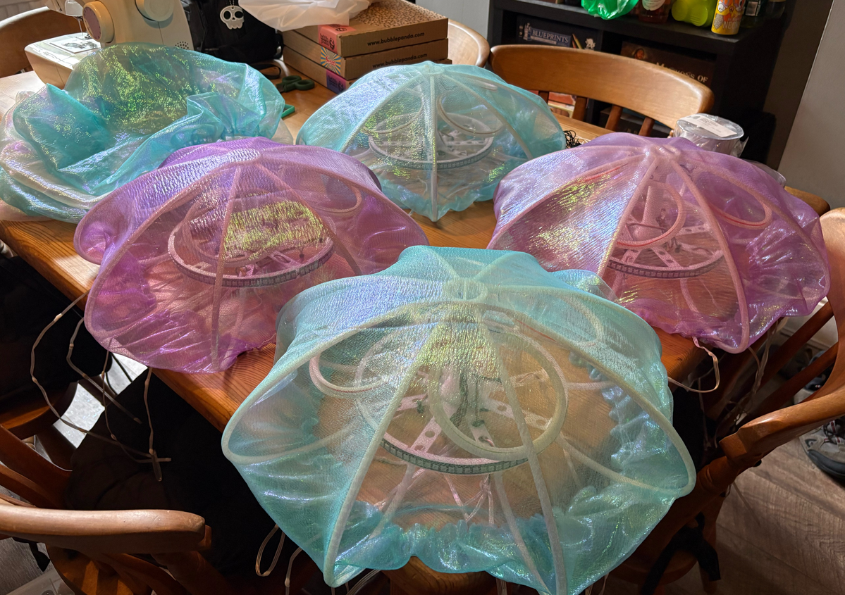

Note that these 'shower caps' are not in any way waterproof, which we'll need to be mindful of at the festival - we have white bin liners on standby if we need to add a layer of emergency waterproofing (might come in handy for the humans too).
🚀 Note from the future - not a single drop of rain fell on Eastnor Deer Park over the course of the festival, so we didn't have to worry about this.
Writing the Code
We started writing the code that drives the jellyfish in MicroPython, since that's the language we're most familiar with, but we quickly found ourselves pushing beyond the level of hardware control it was designed to offer. We knew that we wanted the Picos to be able to drive multiple LED strings. Usually you'd be able to daisy-chain the output of one strip into the input of another, and treat it as a single strip. But we wanted all the tentacles to be hang freely in the air which meant we wouldn't be able to route wires from the end of one strip to the beginning of the next. Coupled with the need to collect digital audio from the I2S microphone, we found that we needed more control over how the Pico's resources were allocated to the hardware.
So we jumped ship to C++, which was a voyage of discovery! Development was done in VSCode, using the Raspberry Pi Pico extension. A Pico Debug Probe made it really easy to flash code without constantly loading up boot selector mode, and to debug code running in real time. We ended up writing custom PIO programs so we could manage which state machines managed which LED string and the microphone. C++ also has the advantage of running much faster on the Pico, which is useful for all the number crunching needed for audio analysis. The dual-cores of the Pico also came in handy, with one core given over entirely to animations while the other stays free to pick up on things like button presses.
The backbone of the animation engine is a class which gives each LED pixel (and each PWM noodle) a position in 3D space. That makes it easy to drive cool effects with waves washing up and down the tentacles, or coloured motes drifting over the body of the jellyfish. The microphone data meant we could calculate ambient volume, as well as a Fast Fourier transform for spectrum analysis so we can drive animations in time with music or a beat.
Alex comments that, with hindsight, he's not sure the digital microphones were the best choice for this project. About half the software development time ended up being spent working out how to get a clean bitstream from the INMP441 microphones. The digital microphones give a great signal once they're working, but really an analog microphone would probably have been much faster!
If you'd like to see the code, it's all available on GitHub:
Here's the view from my desk whilst microphone testing was happening:
And here's some more microphone testing:
🚀 Note from the future - Alex thinks he was too hard on these digital microphones. They were a bit of a faff to sort out but they were picking up on the music way over from the other side of the camp. The auto-ranging in the code meant they worked just as well when you shouted directly at them (and a lot of folks enjoyed shouting directly at them!). So on reflection, he's glad he put the effort in to make them work.
The Finished (ish) Product
Here's the current state of things, three finished Jellys running final (ish) code - I'm sure we'll tinker with it in the field. The one on the right is one of the prototypes, which is why the effects look different.
And a precariously piled fluther of Jellys waiting to be transported to EMF... somehow.
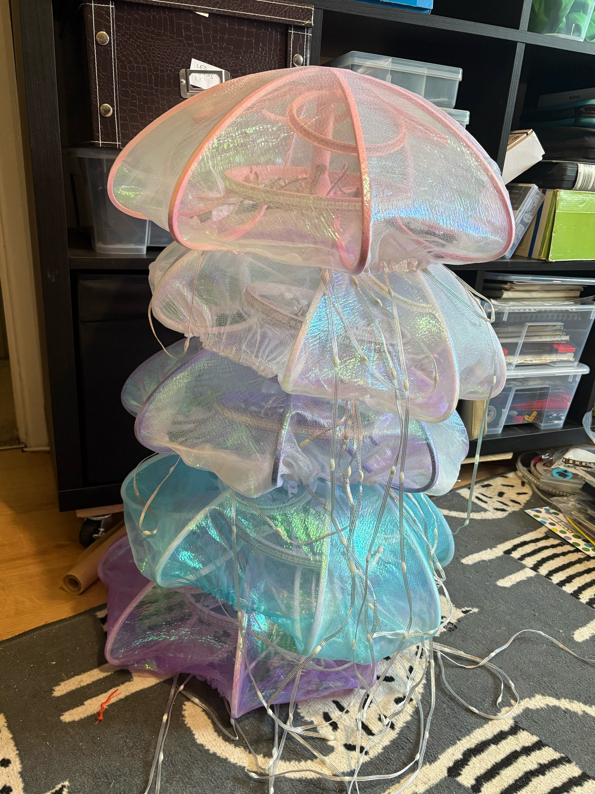
That's all for now - we'll hopefully have some more photos and videos to share of the finished installation after the festival.
🚀 How It Went
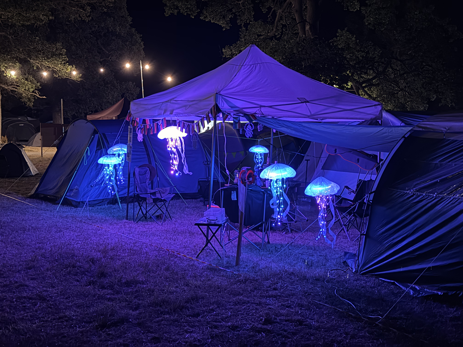
It went great - EMF was, as always, a joyous and inspiring time. Thanks if you came and said hello, or talked/yelled/meowed at our jellyfish. It was lovely to chat to folks, exchange stickers and explain many times that Sheffield is not, in fact, by the sea :)
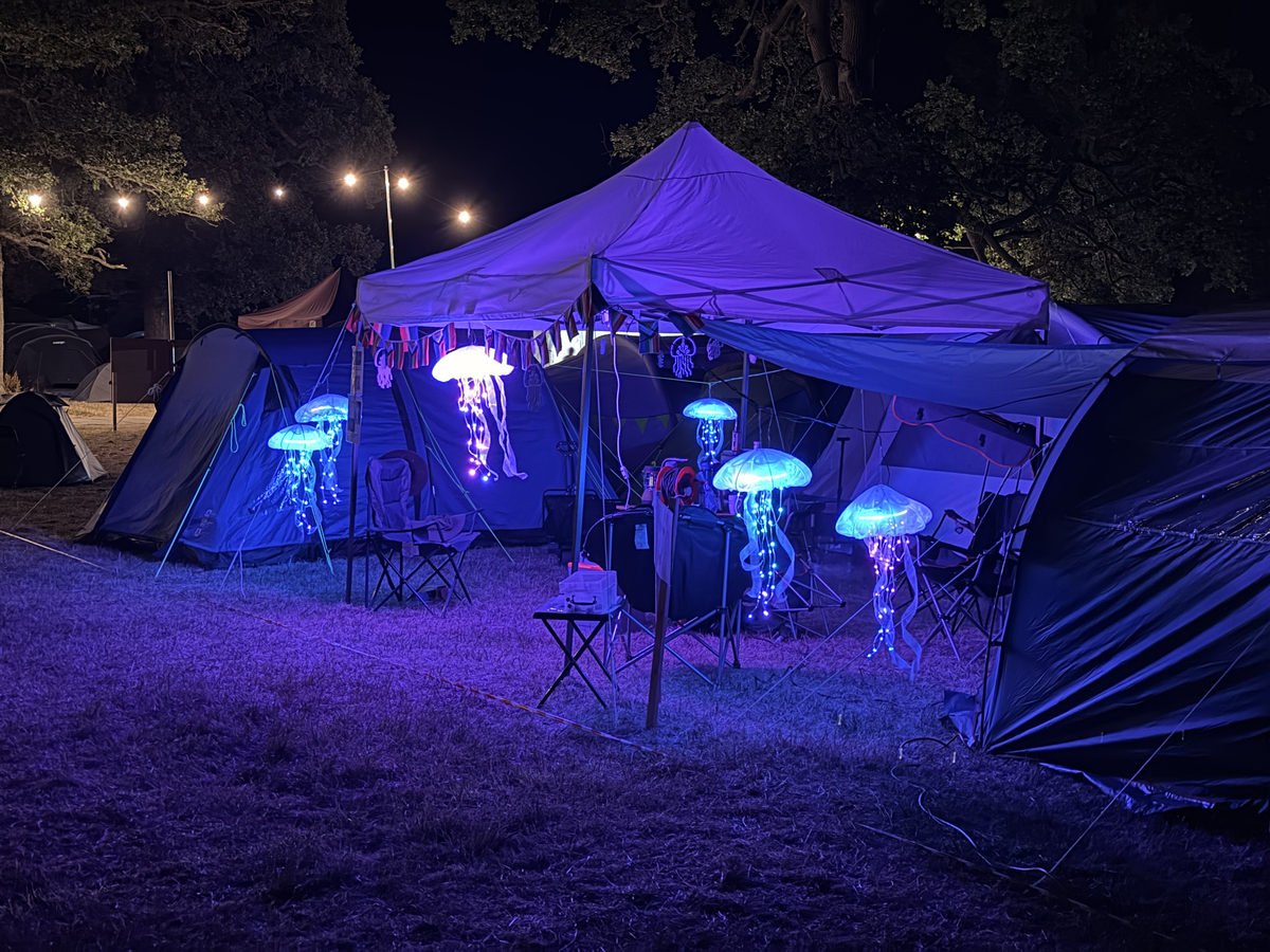
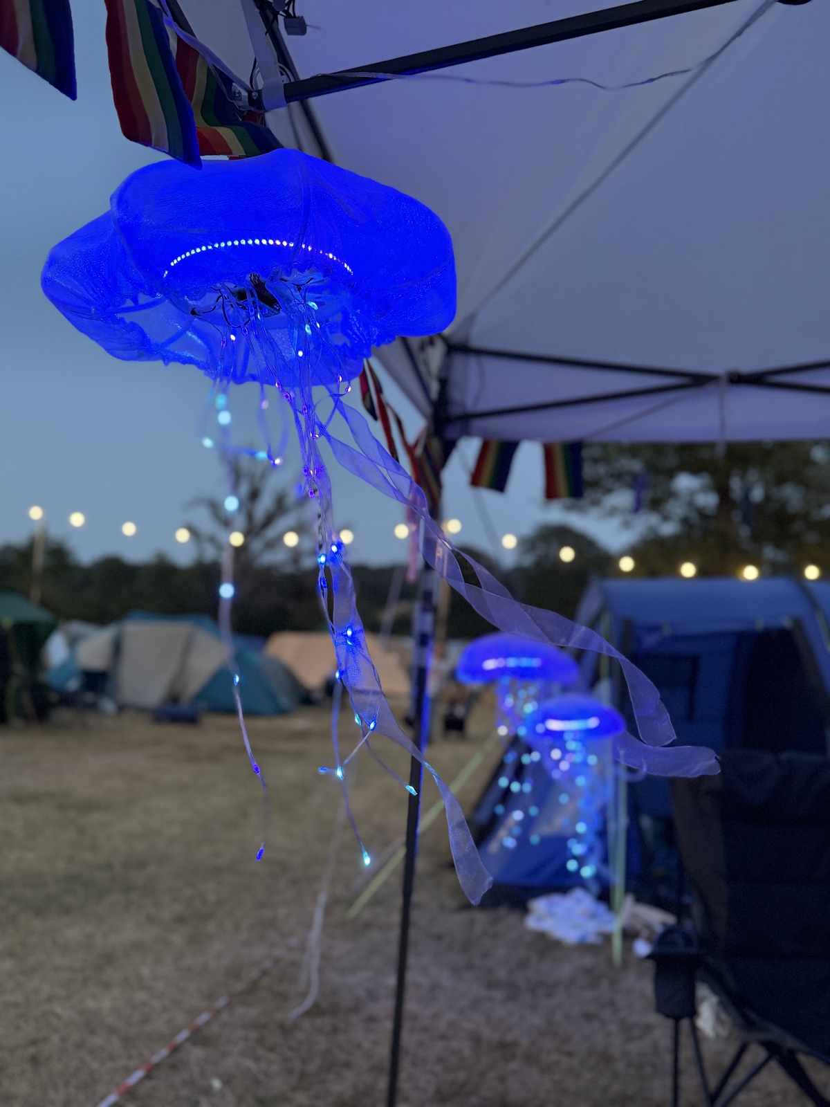
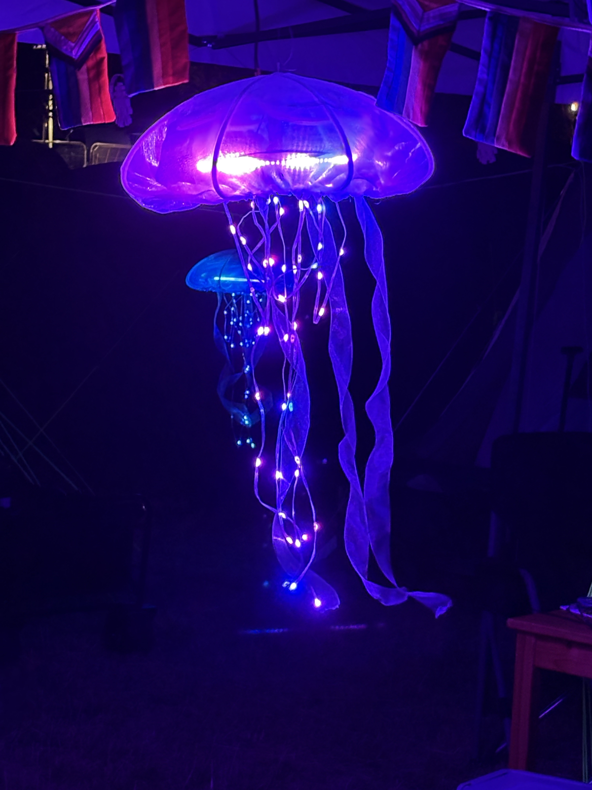
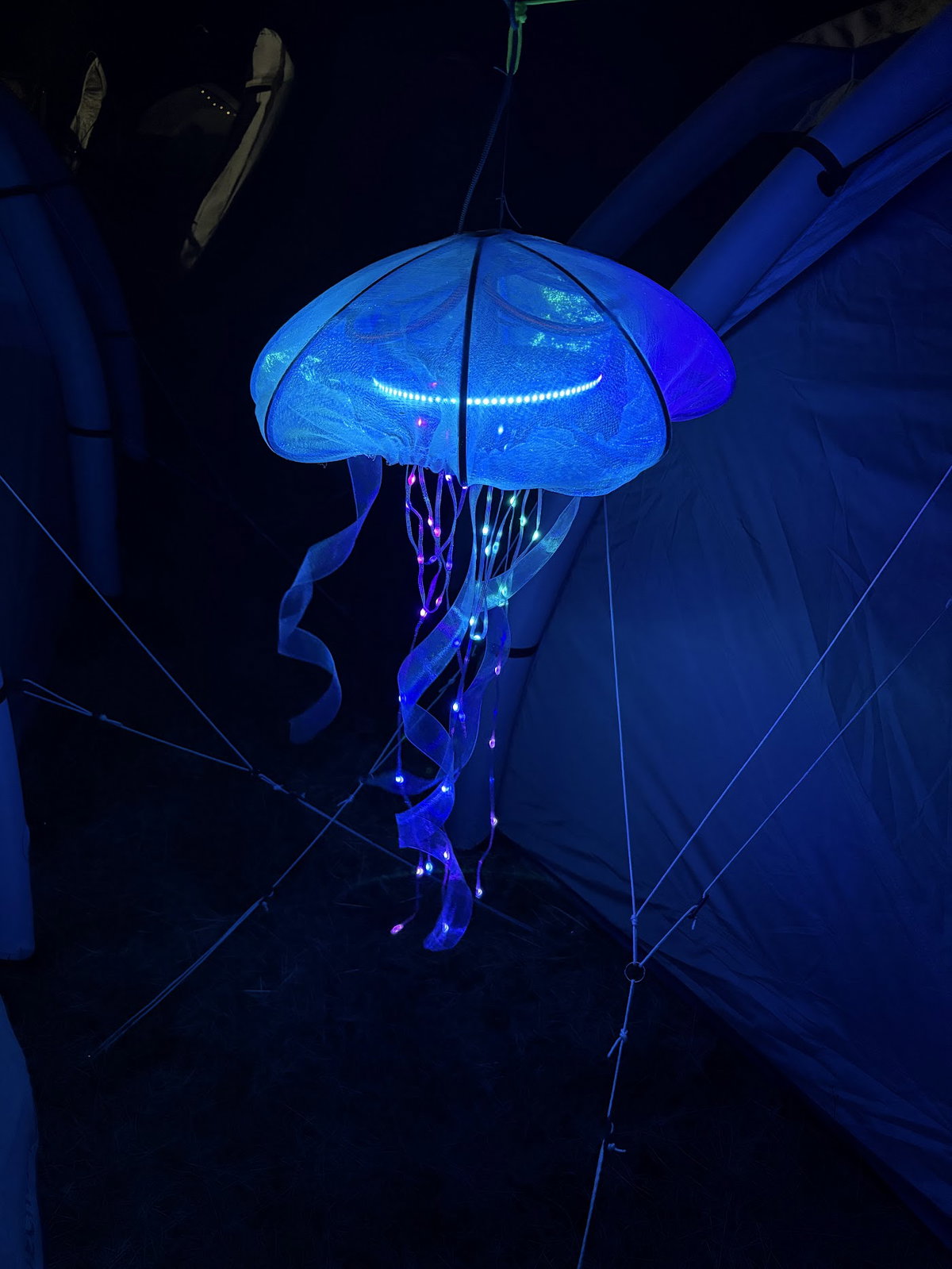
Melty plastic aside, we were very pleased with how the jellyfish looked and the sound reactive effects worked really well - they were pulsing very nicely in time to the beats from Null Sector, even right from the other end of the site. We enjoyed creating a liminal blue-and-purple space in the middle of family camping and have lots of plans for next time.
Here's some photos and videos of the finished installation!